- 您现在的位置:买卖IC网 > Sheet目录234 > MDP1603110RGE04 (Vishay Dale)RES ARRAY 110 OHM 8 RES 16-DIP
MDP 01, 03, 05
www.vishay.com
Vishay Dale
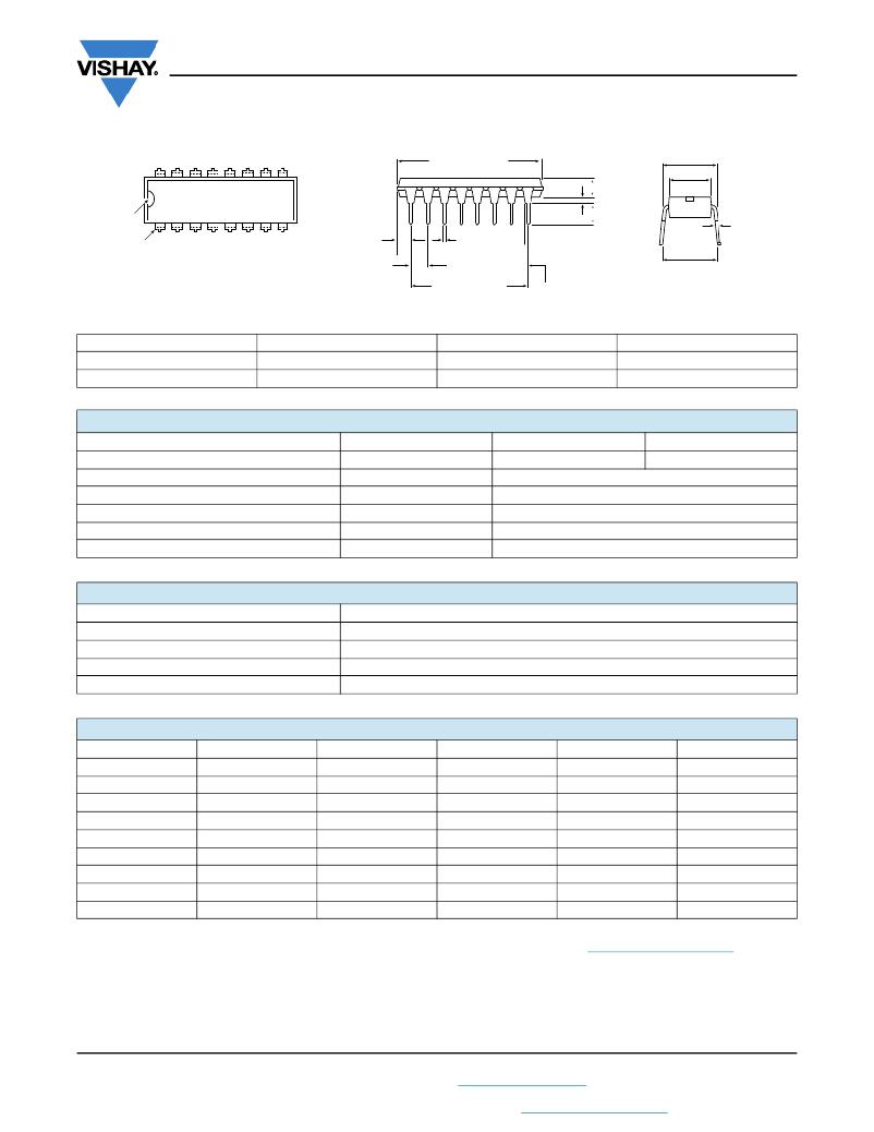
DIMENSIONS in inches (millimeters)
0.310 ± 0.010
A ± 0.010 (0.254)
0.120 ± 0.005
(3.05 ± 0.127)
(7.87 ± 0.254)
0.250 ± 0.005
(6.35 ± 0.127)
0.030
Pin #1
(0.762) Typ.
0.010 + 0.005
Identification
Pin #1
0.075 ± 0.015
(1.90 ± 0.381)
0.018 ± 0.003
(0.457 ± 0.076)
0.130 + 0.015
- 0.010
(3.30 + 0.381
- 0.002
(0.254 + 0.127
- 0.051)
0.100 ± 0.010
(2.54 ± 0.254)
Non-Accumulative Tol.
"C" Spaces
B ± 0.010 (0.254)
0.050 ± 0.005
(1.27 ± 0.127)
- 0.254)
0.290 Min.
0.320 Nom.
0.360 Max.
(7.37 Min.
8.13 Nom.
9.14 Max.)
GLOBAL MODEL
MDP 14
MDP 16
A
0.750 (19.05)
0.850 (21.59)
B
0.600 (15.24)
0.700 (17.78)
C
6
7
TECHNICAL SPECIFICATIONS
PARAMETER
Package Power Rating (Maximum at +70 °C)
Voltage Coefficient of Resistance
Dielectric Strength
Insulation Resistance
Operating Temperature Range
Storage Temperature Range
UNIT
W
V eff
V AC
?
°C
°C
MDP14
1.73
< 50 ppm typical
200
> 10 000M minimum
-55 to +125
-55 to +150
MDP16
1.92
MECHANICAL SPECIFICATIONS
Marking Resistance to Solvents
Solderability
Body
Terminals
Weight
IMPEDANCE CODES
Permanency testing per MIL-STD-202, method 215
Per MIL-STD-202, method 208E
Molded epoxy
Solder plated leads
14 pin = 1.3 g; 16 pin = 1.5 g
CODE
500B
750B
800C
990A
101C
111C
121B
121C
131A
R 1 ( ? )
82
120
130
160
180
180
180
220
220
R 2 ( ? )
130
200
210
260
240
270
390
270
330
CODE
141A
181A
191A
221B
281B
381B
501C
102A
202B
R 1 ( ? )
270
330
330
330
560
560
620
1.5K
3K
R 2 ( ? )
270
390
470
680
560
1.2K
2.7K
3.3K
6.2K
Note
? For additional impedance codes, refer to the Dual Terminator Impedance Code Table document ( www.vishay.com/doc?31530 ).
Revision: 12-Sep-13
2
Document Number: 31511
For technical questions, contact: ff2aresistors@vishay.com
THIS DOCUMENT IS SUBJECT TO CHANGE WITHOUT NOTICE. THE PRODUCTS DESCRIBED HEREIN AND THIS DOCUMENT
ARE SUBJECT TO SPECIFIC DISCLAIMERS, SET FORTH AT www.vishay.com/doc?91000
发布紧急采购,3分钟左右您将得到回复。
相关PDF资料
MEC1-160-02-F-D-EM2
CONN EDGE CARD DL 120POS SMD
MEC1-170-02-S-D-A-K
CONN EDGE CARD DL 140POS SMD
MEC1-170-02-S-D-A
CONN EDGE CARD DL 1MM 140POS SMD
MEC6-170-02-S-DV-A
CONN EDGE CARD DL 140POS SMD
MEC8-130-02-L-D-RA1
CONN EDGE CARD DL 60POS SMD
MEC8-150-01-L-DV-A
CONN EDGE CARD DL 100POS SMD
MECT-110-01-MM-D-RA1
CONN RECEPT XFP 20POS SMD R/A
MENB1010A4803B01
POWER SUPPLY SWITCHER 12W 48V
相关代理商/技术参数
MDP1603120KGD04
功能描述:电阻器网络与阵列 16pin 120Kohms 2% Isolated RoHS:否 制造商:Vishay/Thin Film 产品类型:Networks 电路类型:Divider 电阻器数量: 电阻数值:10 kOhms 容差:0.1 % 温度系数: 管脚数量:3 工作温度范围:- 55 C to + 155 C 尺寸:1.02 mm W x 3.05 mm L x 1.4 mm H 引线间隔: 端接类型:SMD/SMT 封装:Reel
MDP1603120KGE04
功能描述:电阻器网络与阵列 16pin 120Kohms 2% Isolated RoHS:否 制造商:Vishay/Thin Film 产品类型:Networks 电路类型:Divider 电阻器数量: 电阻数值:10 kOhms 容差:0.1 % 温度系数: 管脚数量:3 工作温度范围:- 55 C to + 155 C 尺寸:1.02 mm W x 3.05 mm L x 1.4 mm H 引线间隔: 端接类型:SMD/SMT 封装:Reel
MDP1603120RGD04
功能描述:电阻器网络与阵列 16pin 120ohms 2% Isolated RoHS:否 制造商:Vishay/Thin Film 产品类型:Networks 电路类型:Divider 电阻器数量: 电阻数值:10 kOhms 容差:0.1 % 温度系数: 管脚数量:3 工作温度范围:- 55 C to + 155 C 尺寸:1.02 mm W x 3.05 mm L x 1.4 mm H 引线间隔: 端接类型:SMD/SMT 封装:Reel
MDP1603120RGE04
功能描述:电阻器网络与阵列 16pin 120ohms 2% Isolated RoHS:否 制造商:Vishay/Thin Film 产品类型:Networks 电路类型:Divider 电阻器数量: 电阻数值:10 kOhms 容差:0.1 % 温度系数: 管脚数量:3 工作温度范围:- 55 C to + 155 C 尺寸:1.02 mm W x 3.05 mm L x 1.4 mm H 引线间隔: 端接类型:SMD/SMT 封装:Reel
MDP160312K0GD04
功能描述:电阻器网络与阵列 16pin 12Kohms 2% Isolated RoHS:否 制造商:Vishay/Thin Film 产品类型:Networks 电路类型:Divider 电阻器数量: 电阻数值:10 kOhms 容差:0.1 % 温度系数: 管脚数量:3 工作温度范围:- 55 C to + 155 C 尺寸:1.02 mm W x 3.05 mm L x 1.4 mm H 引线间隔: 端接类型:SMD/SMT 封装:Reel
MDP160312K0GE04
功能描述:电阻器网络与阵列 16pin 12Kohms 2% Isolated RoHS:否 制造商:Vishay/Thin Film 产品类型:Networks 电路类型:Divider 电阻器数量: 电阻数值:10 kOhms 容差:0.1 % 温度系数: 管脚数量:3 工作温度范围:- 55 C to + 155 C 尺寸:1.02 mm W x 3.05 mm L x 1.4 mm H 引线间隔: 端接类型:SMD/SMT 封装:Reel
MDP160312R0GD04
制造商:Vishay Dale 功能描述:RES THKFLM NET 12 OHM 2% 1.92W 100PPM/ C ISOL 16DIP PIN TH - Bulk
MDP1603150G
功能描述:电阻器网络与阵列 16pin 15ohms 2% Isolated RoHS:否 制造商:Vishay/Thin Film 产品类型:Networks 电路类型:Divider 电阻器数量: 电阻数值:10 kOhms 容差:0.1 % 温度系数: 管脚数量:3 工作温度范围:- 55 C to + 155 C 尺寸:1.02 mm W x 3.05 mm L x 1.4 mm H 引线间隔: 端接类型:SMD/SMT 封装:Reel
